Welcome to Our Garage
Daytona Coupe, 289 and 427 Cobras
-15-
Daytona Coupe Cobra -
Exhaust System
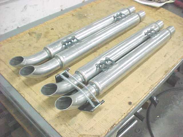
The Coupes had an unusual exhaust system design that utilized a 2 into 1 piping arrangement. This layout routed pairs of engine cylinders into 4 separate mufflers with 2 mufflers per side. The mufflers shown in the following photo have been welded to the exhaust tips and the slip joints. Also shown on the lower muffler pair is one of the spring brackets required to retain the dual muffler to each side of the car.

It appears that each car had its own unique header pipe routing scheme. It is assumed that this was due in part to the subtle chassis and sheet metal differences between the cars, but also due in large part to the fact that each car's exhaust was fabricated with only occasional reference to its sister car. The only consistency in the systems were the uniformity of the connection of the same number cylinders together in the primary pipes and mufflers. The following photo shows the header flange with approximately 1" long pipe stubs mounted on a mockup block in the chassis.

Next the mufflers were mounted to the side of the car and then the routing of the primary pipes between the stub outs and the mufflers was tackled.
The previous photos showed the beginnings of the header and muffler fabrication. In the following photos the headers are almost completed. The first photo shows a few of the tools made to make the 2 into 1 collector that were used in the coupes. The tooling was relatively simple and consisted of one piece (the upper round dark steel) to maintain the original pipe diameter and the second piece (the lower piece held in the vise) that provided a hammer form to shape the collector transitions. The center piece is a sample of the 16 gauge tubing prior to the shaping operation.

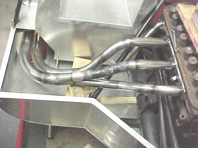
The headers were a relatively straightforward fabrication task. Blank flange plates and mandrel U-bends were purchased. Flexible electrical conduit was used to obtain an idea of the basic routing of each primary pipe. The following photos show the left and right side headers almost completed. The remaining task is to unbolt the flange plates from the mockup motor and finish welding the primary pipes to the flanges. The hose clamp seen on the second pipe back on the right side is a simple but very effective construction technique that was used to hold the tubes in perfect alignment while tack welding. The hose clamp is slotted on two opposite sides and tightened onto the pipes. The slots provide access to TIG tack the tubes together.

