Welcome to Our Garage
Daytona Coupe, 289 and 427 Cobras
-31-
Daytona Coupe Cobra -
Weber Carbureted Engine Installation
This section covers some of the "adventures" that I had installing the Webers on the Daytona.
Why Webers
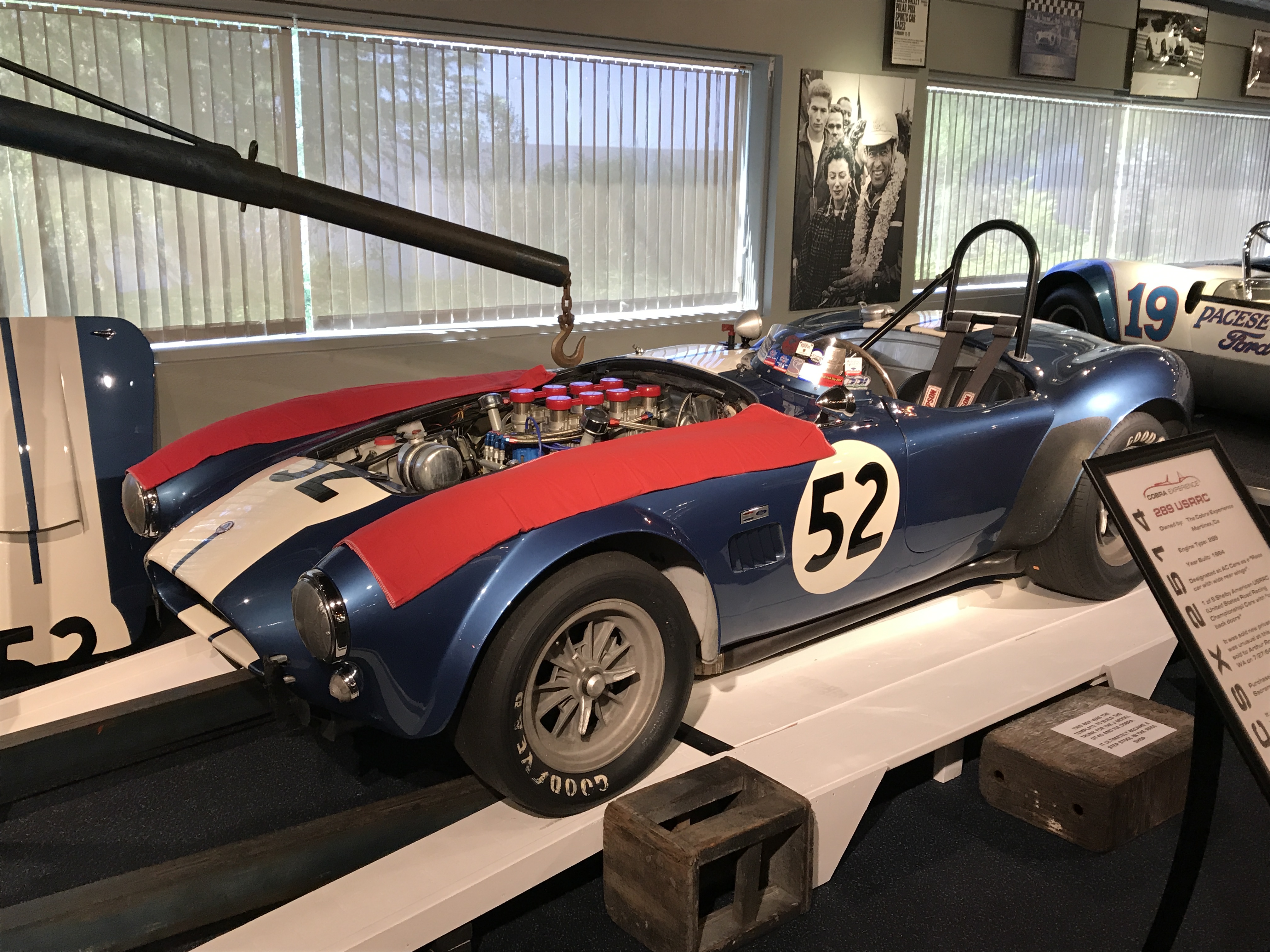
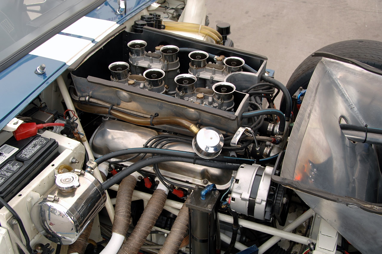
48 IDA Weber carburetors were the state of the art carburetion for road racing in the 1960's. They were installed on both the 289 Cobra roadsters and Daytona coupes. The following photos show examples of Webers installed on an original Daytona coupe and an original 289 Cobra roadster.
The following photo is of original Daytona coupe chassis CSX2601 with Webers:
Webers on original 289 USRRC Cobra chassis number CSX2514 photo
Weber variations used on Cobras
The original manifolds for the Webers used on the 289 Cobras were made in two versions. One variation mounted the Webers with the fuel inlet lines all facing toward the outside of the car and was sometimes referred to as the "Cobra manifold" or "opposed carburetor manifold" design. The second variation mounted all of the carburetors in the same direction with all fuel inlets facing the driver side of the car and was often referred to as the "GT350 manifold" or the "non - opposed carburetor manifold" design.
Historical photos of the original Daytona Coupes show both manifolds being used on the cars, although the “Cobra” style is more commonly seen. I have both style manifolds and debated which to use, but finally decided on the less common GT350 style.
Weber carburetors have a reputation for significantly increasing the responsiveness and power output of an engine; however, they are also known for being finicky to tune for best performance and drivability. My logic was that rather than breaking in a new car AND a new (potentially temperamental) engine simultaneously, I would deal with them one at a time. Hence the first engine in the coupe was a period correct 289 however; it utilized a single Holley four barrel carburetor rather than a set of four 48 IDA Webers.
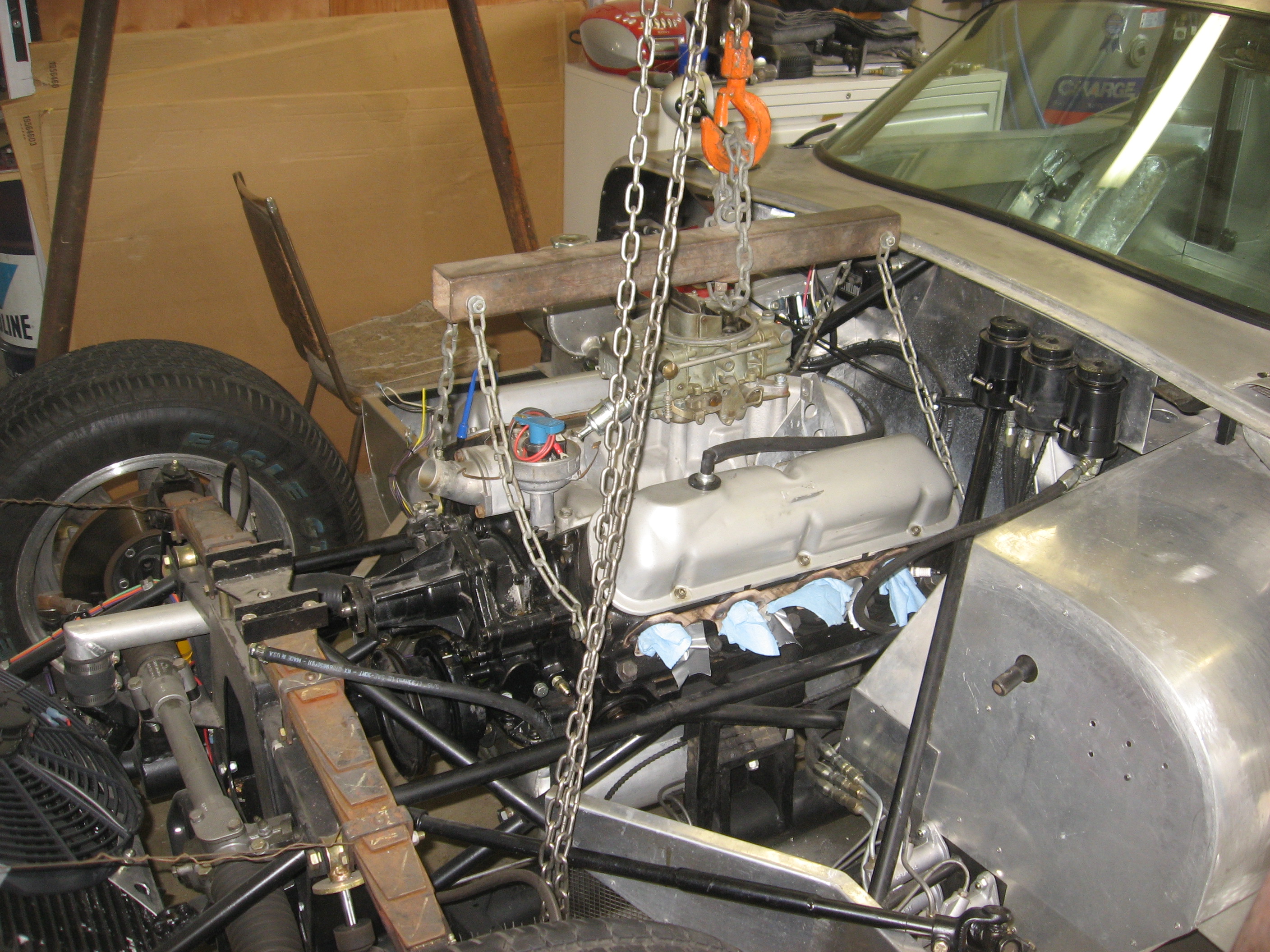
The following photo shows the 289 engine with Holley four barrel carburetor originally installed in the Daytona as it was being removed to make way for the Weber engine.
The Daytona Weber engine
The Coupe now has approximately 9,000 “test” miles on the odometer with the Holley 4 barrel carburetor and I felt confident in the car itself. It was time to install the Webers.
Although my Coupe’s first 289 engine had a reasonable performance camshaft, it was selected for the four barrel carburetor. Weber carburetors, unlike a four barrel carburetor, require a much different camshaft profile to perform effectively. Suffice it to say that most experts recommend the camshaft used in a Weber carbureted engine should provide less intake valve / exhaust valves overlap than a camshaft used with a traditional four barrel carburator. Stated another way, the camshaft lobe separation angle for a Weber engine is increased. Rather than simply bolting the Webers onto the first 289 engine and changing the camshaft, I decided to build a completely new engine with a camshaft having a profile more appropriate for the Webers.
The second 289 engine with a Weber appropriate camshaft was completed, given a brief break-in run on an engine stand and was ready to install into car. The following photo shows the Weber engine on the stand.
Hood bubble version 1.0 "Uh-Oh"
Before installing the new Weber engine, I made a trial fit of the Webers using a spare 289 block and manifold to mock up the linkage and air box. It was at this time that I discovered that the front right Weber air horn had less clearance to the hood bubble than I wanted.
I spent time studying lots of photos for the original six Daytonas hoods and it became obvious that the shape of the hood bubble on my car was not true to the originals. Since all of the original cars had slightly different bubble shapes, it was time to go back to the “drawing board” before installing the new Weber engine to refine the bubble presently on the car. You will soon understabd why I called this bubble version 1.0.
Hood bubble version 2.0
Rather then trying to modify the bubble on the car to provide more Weber air horn clearance, I decided it would be easier to make an entirely new bubble. The original bubble was cut off the hood and a completely new bubble was fabricated. The photo below shows the hood cutout in progress with the “mock up” 289 engine block and a Weber manifold that was used for preliminary layout. The manifold in the photo is an example of the "Cobra" or "opposed carburetor" design.
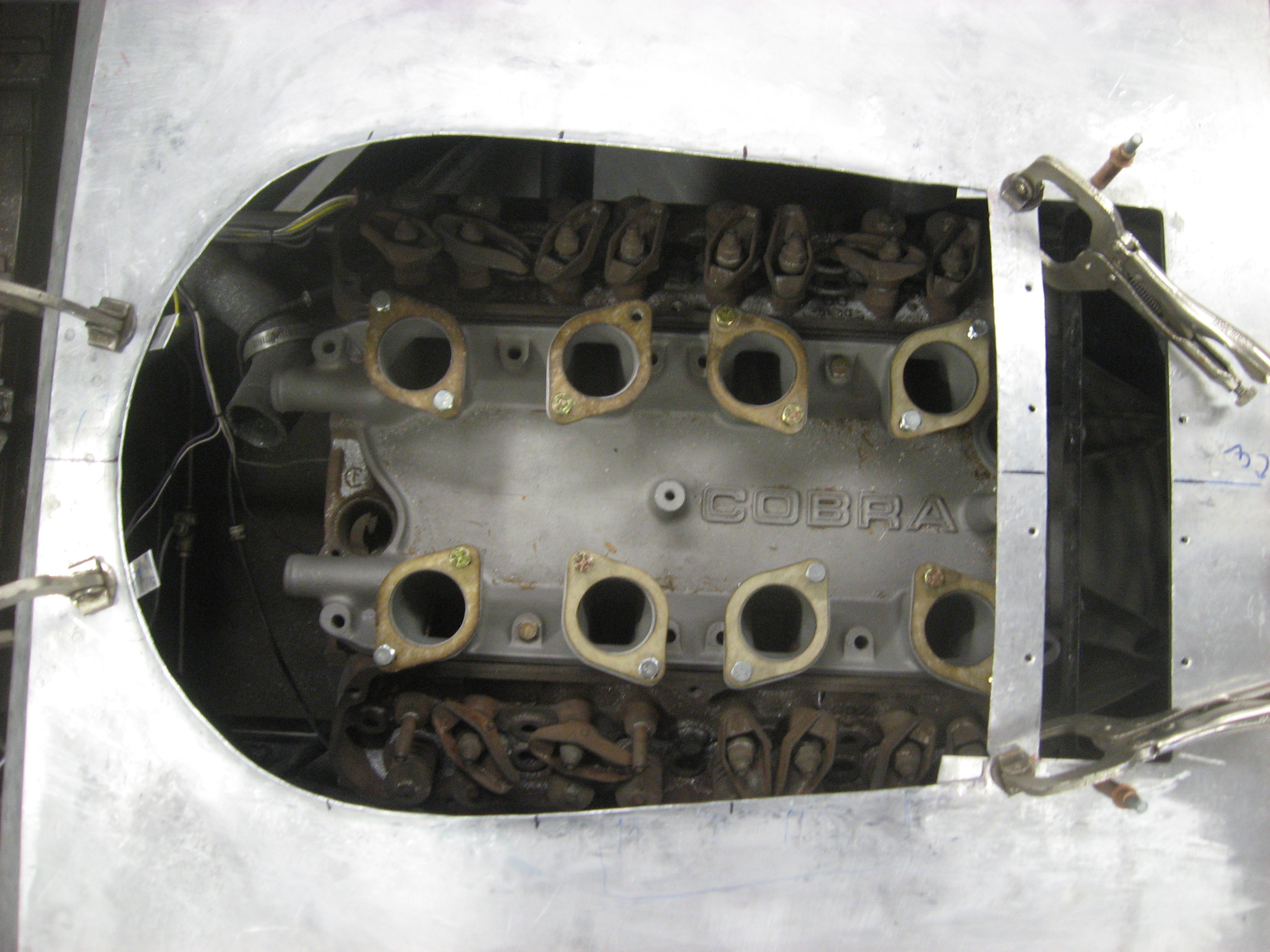
The new bubble (version 2.0) was fabricated and it was time to weld it onto the Daytona’s hood. The new bubble was tacked onto the hood. Rather than using oxyacetelene gas welding, TIG welding was used at this point for both tacking and final welding to minimize the heat input onto the large relatively flat hood. The following photo shows part of this task. The finished version 2.0 bubble mostly welded onto the hood and the metal finishing begun is shown in the following photo.

Version 2.0 bubble did provide the desired clearance above the Weber carburetors. However, something about it just didn’t appeal to my eye.
Hood bubble version 3.0
After more research on the bubble and Webers used on the original Daytonas, it became evident that they utilized Weber carburetors with an optional “short” air horn. It was one of those "duh" moments. The obvious bennefit of the short air horns was they allowed a lower profile of the hood bubble while still providing adequate clearance over the carburetors. It is my understanding that the shorter air horns also provided increased power at the higher RPMs.
I purchased a set of the short air horns (and auxiliary venturi) and installed them on my Webers. When mocked up in my coupe, these did allow a slightly reduced bubble while still maintaining adequate space to the bottom of the hood bubble. The photo below shows the difference in height of the standard air horn (on the right) and the short air horn (on the left).
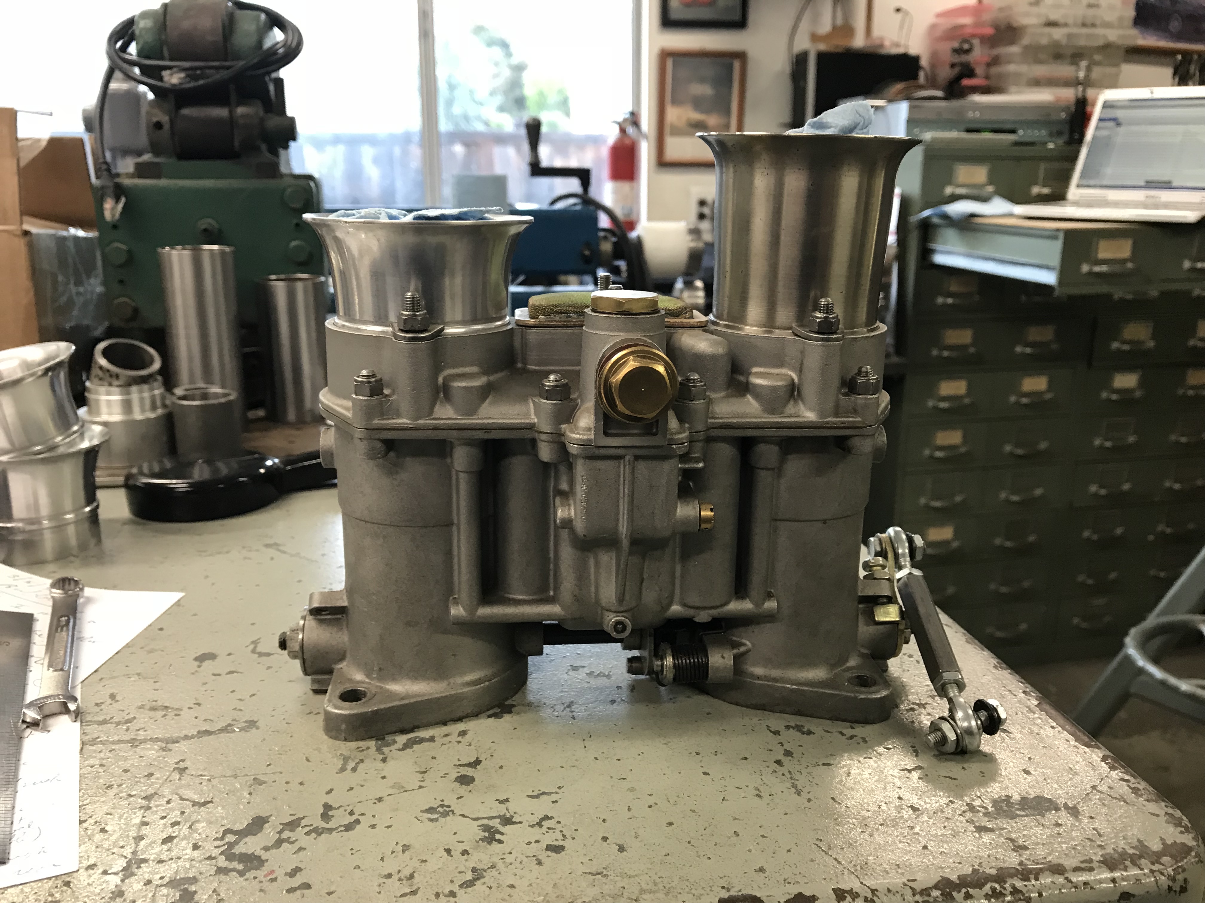
However, after some definite soul searching, I decided to stick with my original concept of usiing the taller air horns (rather than the short horns) even thought they would require a slightly larger hood bubble for clearance. The logc for the decision was based on several considerations:
- Street driving: The car will be used exclusively for street driving; therefore the focuse will be on lower RPM performance.
- Resources: A number of other Cobra replica owners have successfully used the traditional tall air horns so there would be a larger number of enthusiasts to discuss Weber "issues".
- Cobra heritage and proven design: The taller Weber air horns were used in most (all?)original 289 Cobra roadsters. This heritage and the successfulness of the Cobra roadster demonstrates the capabilities of the taller air horn design.
- Flexibility. Should future modifications to the engine become desirable, the taller horns would more easily accomodate alternative engine / manifold configurations. (Although definitely not stock, the idea of a small block 427 engine in the Daytona has some appeal. Installing a longer stroke crankshaft in a 351 cubic inch Ford is simple way to get 427 cubic inches in a small block engine. The 351 Ford with the short Weber air horns would fit under the bubble used for the 289 engine with the tall air horns.
- Originality: Like so many aspects of the original Daytona Cobras, the hood bubble shape differed from car to car. Maintaining a period correct look was therefore more important than creating an exact copy of any one of the original six cars.
It was time to cut the version 2.0 bubble from the hood and start work on a new bubble that had a better look (at least to my eye). Making a long story short, I cut off bubble version 2.0, welded a patch over the hole, formed another bubble (this is bubble version 3.0 if you're keeping count, cut a new hole in the hood and welded the bubble on.
The following photo is version 3.0 tacked to the hood.
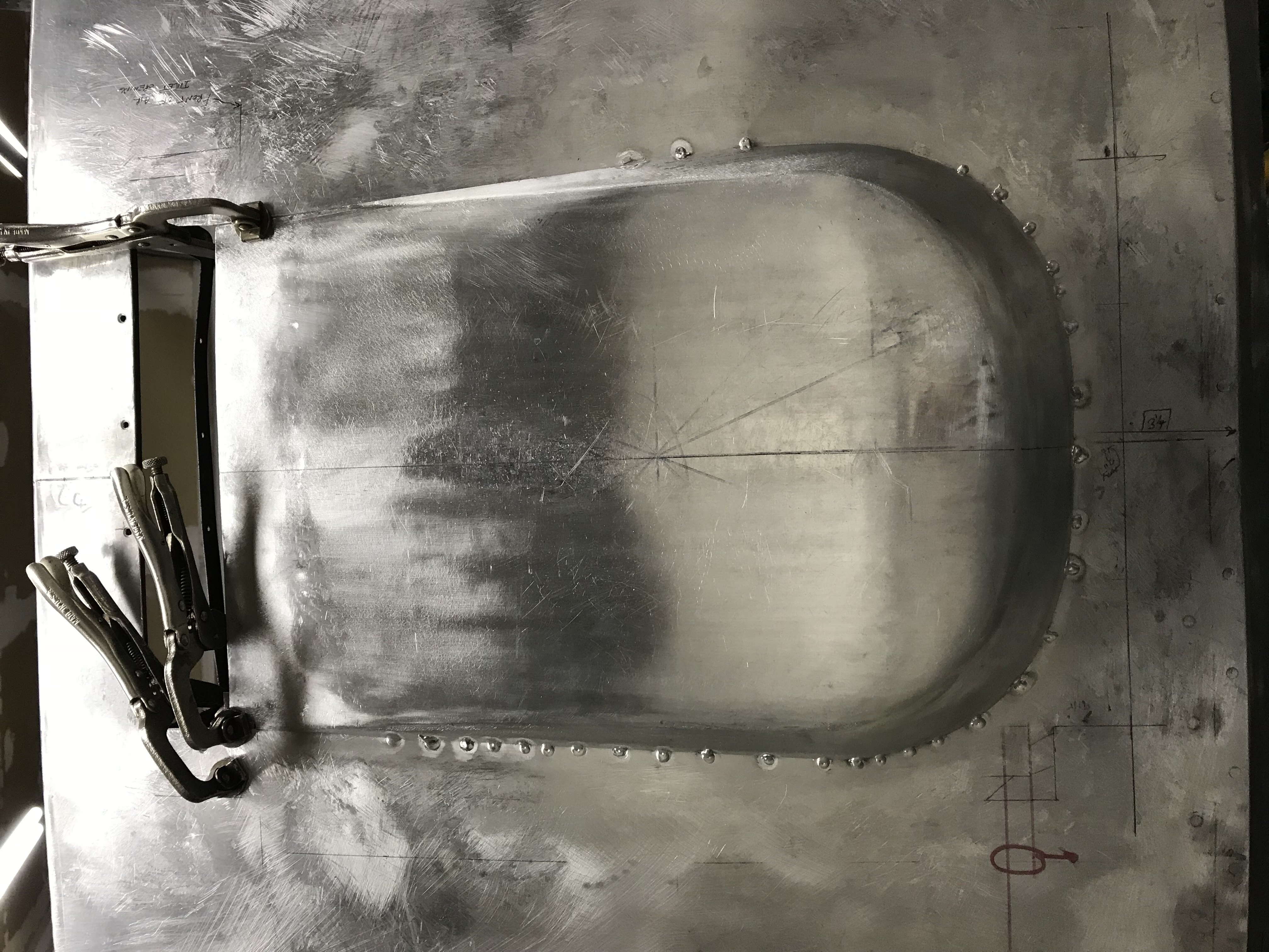
Although not apparent from this view, once again, although it provided the desired clearance to the Webers and it was getting closer to the look I wanted, it was still not quite the way I wanted it.
Bubble version 4.0
One more time.
Off came version 3.0 and on went bubble version 4.0.
I won't bore you with the details of the installation of another new bubble other than the following comments. The new bubble shape was changed only slightly from version 3.0. More importantly, for version 4.0, I changed my installation technique slightly. On the previous bubble (version 3.0), I made the joining weld right at the point where the hood and bubble met. This made metal finishing of the weld line more difficult and harder to keep in perfect alignment. On version 4.0, I formed a 3/4" wide flange on the bubble itself. This flange added a little more time in forming the bubble, but it made welding to the hood and subsequent metal finishing much easier. Lesson learned.
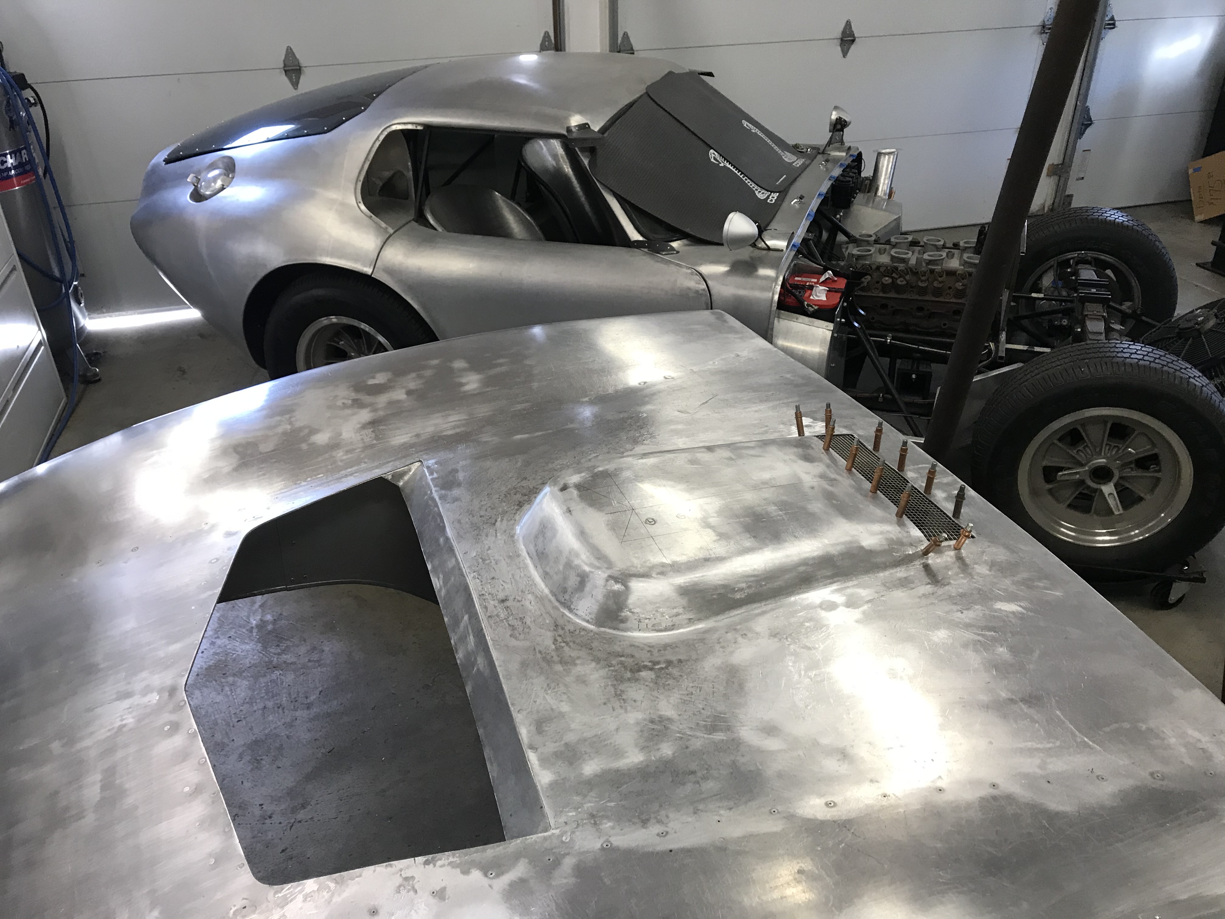
Bottom line is that this bubble is a keeper. I can only imagine the coupe sittig in the background thinking "it's about time". Certainly I couldn't agree more.
The folowing phot shows the version 4.0 bubble welded to the hood and quite a way through the metal finishing process.
