Welcome to Our Garage
Daytona Coupe, 289 and 427 Cobras
-22-
Daytona Coupe Cobra -
Engine Transmission Installation
test
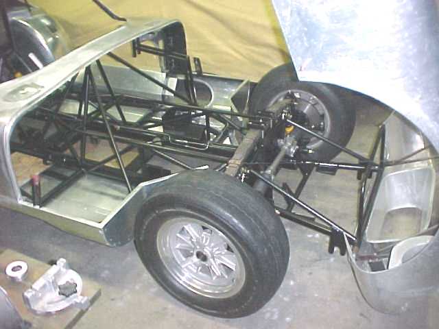
The basic car complete with all of the suspension pieces installed is on the ground awaiting the installation of the engine and transmission pieces.

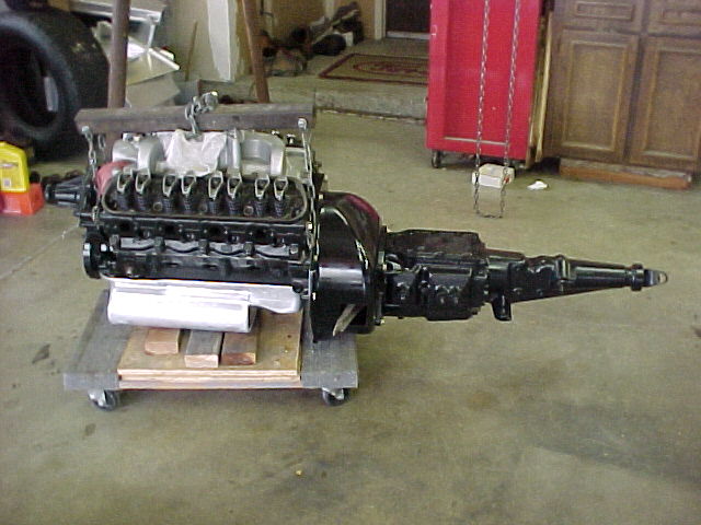
The initial motor will be a mild mechanical cam single four barrel motor (715 CFM Lemans bowl Holley on an original small letter Cobra manifold) running 10:1 compression ala the 289 roadster street cars. After the car is sorted out, the motor will be upgraded to run the Webber carbs shown earlier in the photos. True to originality, the motor is a 1965 block 289. The original coupes utilized the aluminum case Borg Warner transmission, however the unit that I will install initially will be a wide ratio Ford toploader design. In the following photo the motor and transmission have been mated and are awaiting installation in the chassis.

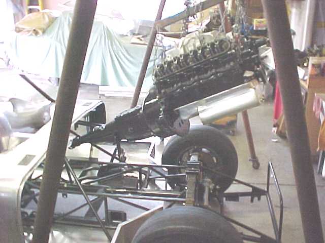
There were two "oops" that occurred at this point. Although the engine and transmission had been installed in the car numerous times for test fitting, they had been installed separately. It didn't take long to figure out that the motor transmission combination wouldn't fit into the chassis as a single unit. The extra triangulation tubes in and around the tunnel area added significantly to the chassis rigidity, however they also minimize the available working space. The clearances are just not there to install the engine and transmission as a single assembly. Although installing the complete engine transmission assembly into a 289 roadster is not a problem, it wouldn't fit into the coupe. I have seen some roadsters that have modified the center transmission cross member (by making it removable) so that the trans can be removed from below. This modification would work well in the coupe and might be considered at a future date. The following photos shows the assembly just before I figured out that the clearance problem. Shortly after this photo the transmission was removed from the motor and installed separately.

The drive shaft, alternator, shifter lever, clutch throwout assembly, distributor and carburetor were next installed. It was looking like things were going smoothly, when the second "oops" occurred. Being clever, I had left the firewall out of the car to allow better access to the engine / transmission and related pieces. Although these panels had also been installed several times during the construction, I had not figured on the importance of the sequence of installation. With the engine in the car, the central firewall piece was to large to be installed after the engine (and more particularly the scattershield) was in place. For a few minutes, I seriously contemplated cutting the offending firewall panel into two pieces to facilitate its installation, however finally the ultimate goal prevailed and the motor and transmission was pulled to allow the firewall to be installed in one piece.
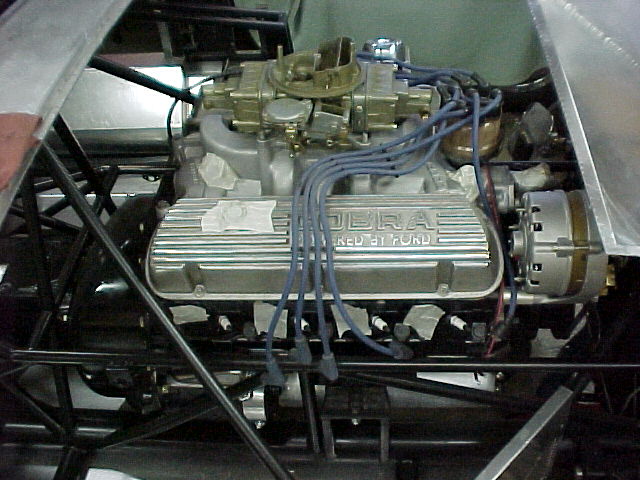
I didn't take any good photos which showed how close the aluminum firewall panel was to the engine (and bell housing); however, the following photo shows just how tight the clearances are in the engine bay. Note the small diameter horizontal bracing tube located just to the rear of the bell housing (running from the left to right side of the engine bay upper bracing tubes) and the minimal clearance between it and the bell housing. The "problem" aluminum firewall panel (the one that I almost cut) is mounted on top of and slightly in front of this horizontal tube. Tight indeed!
