Welcome to Our Garage
Daytona Coupe, 289 and 427 Cobras
-36-
Daytona Coupe Cobra -
Brake & Clutch Master cylinders -
Feed lines
In my original build, the clutch and brake fluid reservoir cans were mounted on a small aluminum panel located above the driver footbox and in front of the fire wall. They were connected to their corresponding master cylinders with an AN-3 size Aeroquip cloth braided hose. This was done to provide a more period correct look to the plumbing. The hose was routed from the reservoirs, across the top rear of the foot box, down the side of the box to just above the main frame rail, then forward where it was transistioned to a 3/16" steel tube to bend back around the front of the box and to it's final connection to the master cylinders.
Even though the AN-3 hose was relatively small, it did add considerable congestion in the small and already crowed area between the foot box and the engine and bell housing.
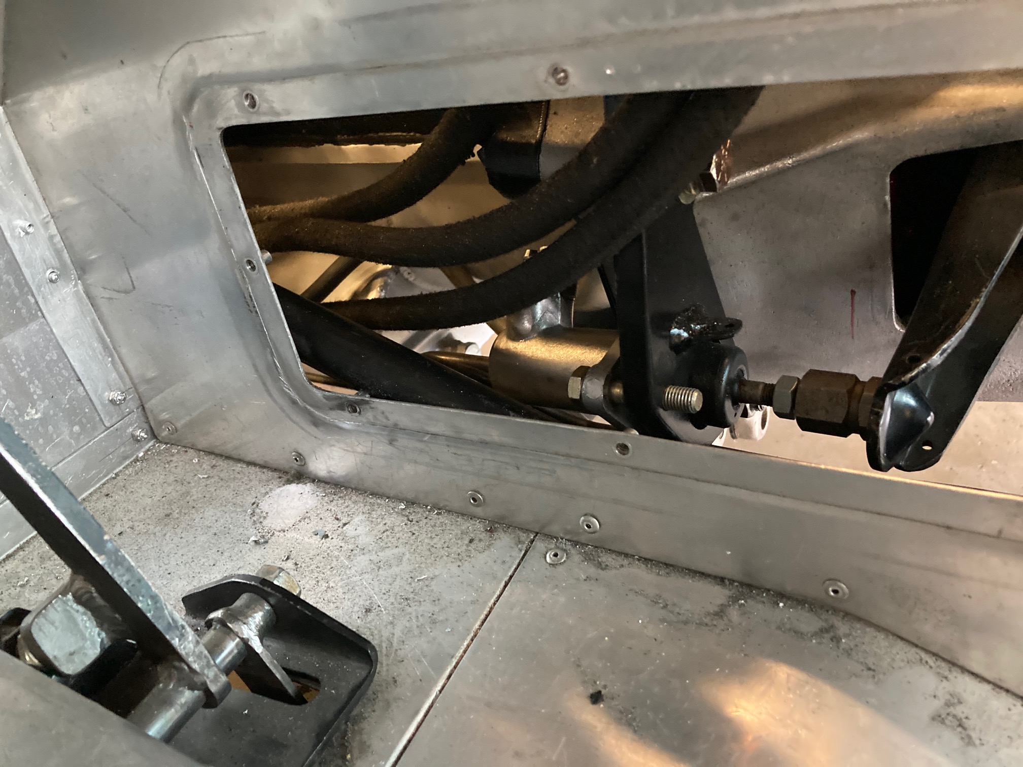
There is a small removable aluminum panel in the side of the footbox to access the slave cylinder for adjustment and bleeding; however, the usefullness of the access hole was diminished because of the Aeroquip hoses.
The following photo shows the access hole in the footbox and the Aeroquip hoses that limited the usefulness of the panel.

After living with the restricted access to the clutch slave cylinder during the original testing of the car, I decided that some type of modification was required. The braided cloth Aeroquip hose had to go.
Review of a number of contemporary photos of the oringal Daytonas show that some of the cars now use a braided stainless steel AN hose routed across the top of the foot box then down the front of the box to the master cylinders. Adopting this routing would certainly eliminate the "hose congestion" in the vicinity of the slave cylinder. Although I liked the routing, I was not ready to move to the "stainless steel AN hose look on my Daytona recreation.
The solution that I adopted combined two features of the originals that I liked and at least to my eye looked more period correct.
- Steel tubing to interconnect the reservoirs with the master cylinders (versus a braided stainless steel hose)
- Routing the reservoir to master cylinder interconnection tubing more directly (across the top and down the front of the footbox)
Because of all the bends required, the use of a steel tubing was more trouble to fabricate than a stainless steel AN hose, but I like the look. Additionally, the steel tubing was slightly smaller in diameter further adding to the compactness of the final installation.
The revised routing of the tubing between the reservoirs and the master cylinders now more closely follows the layout of the original cars (at least some of them).
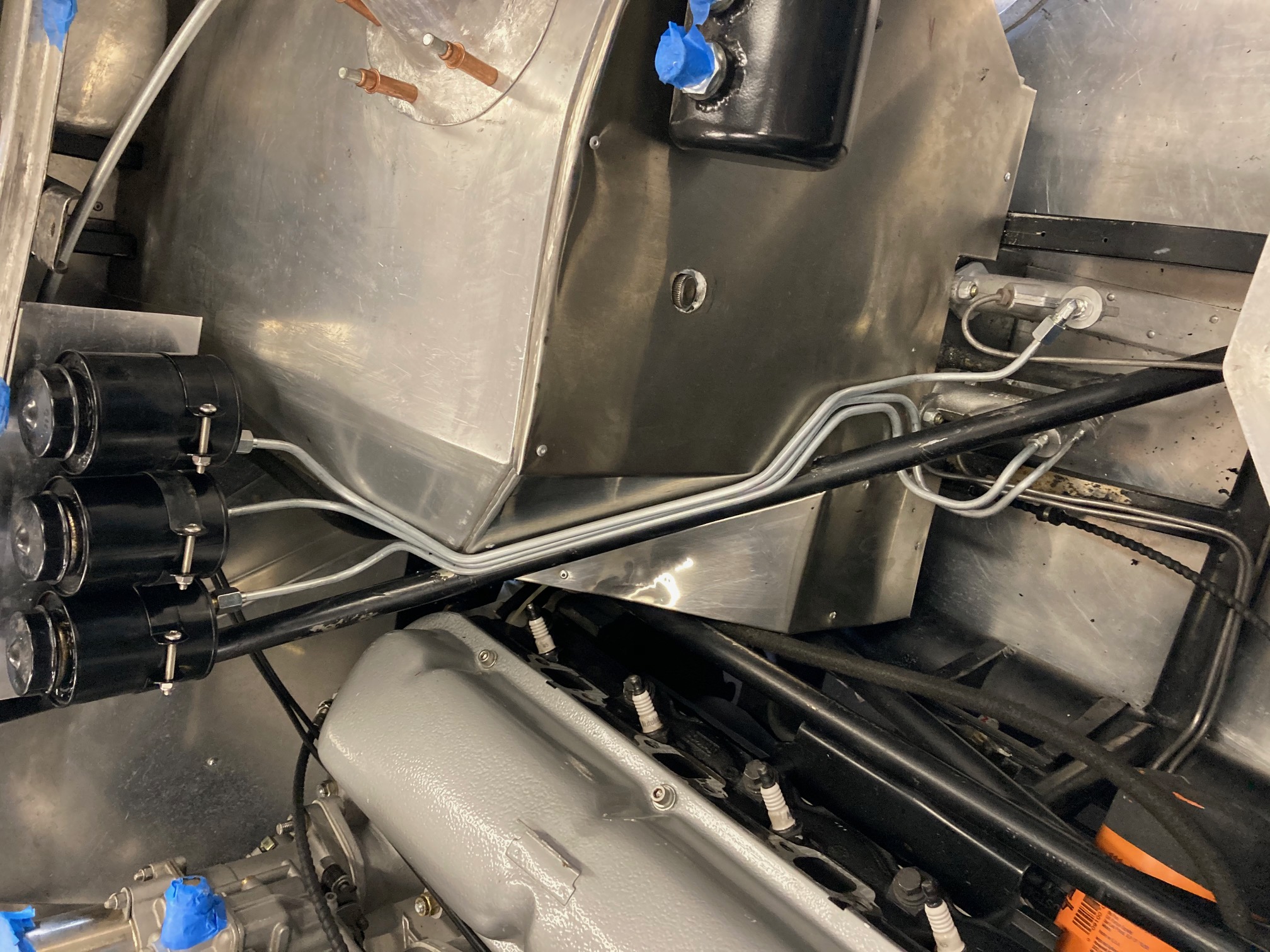
The following photos show the new steel tube being fabricated and installation almost complete.

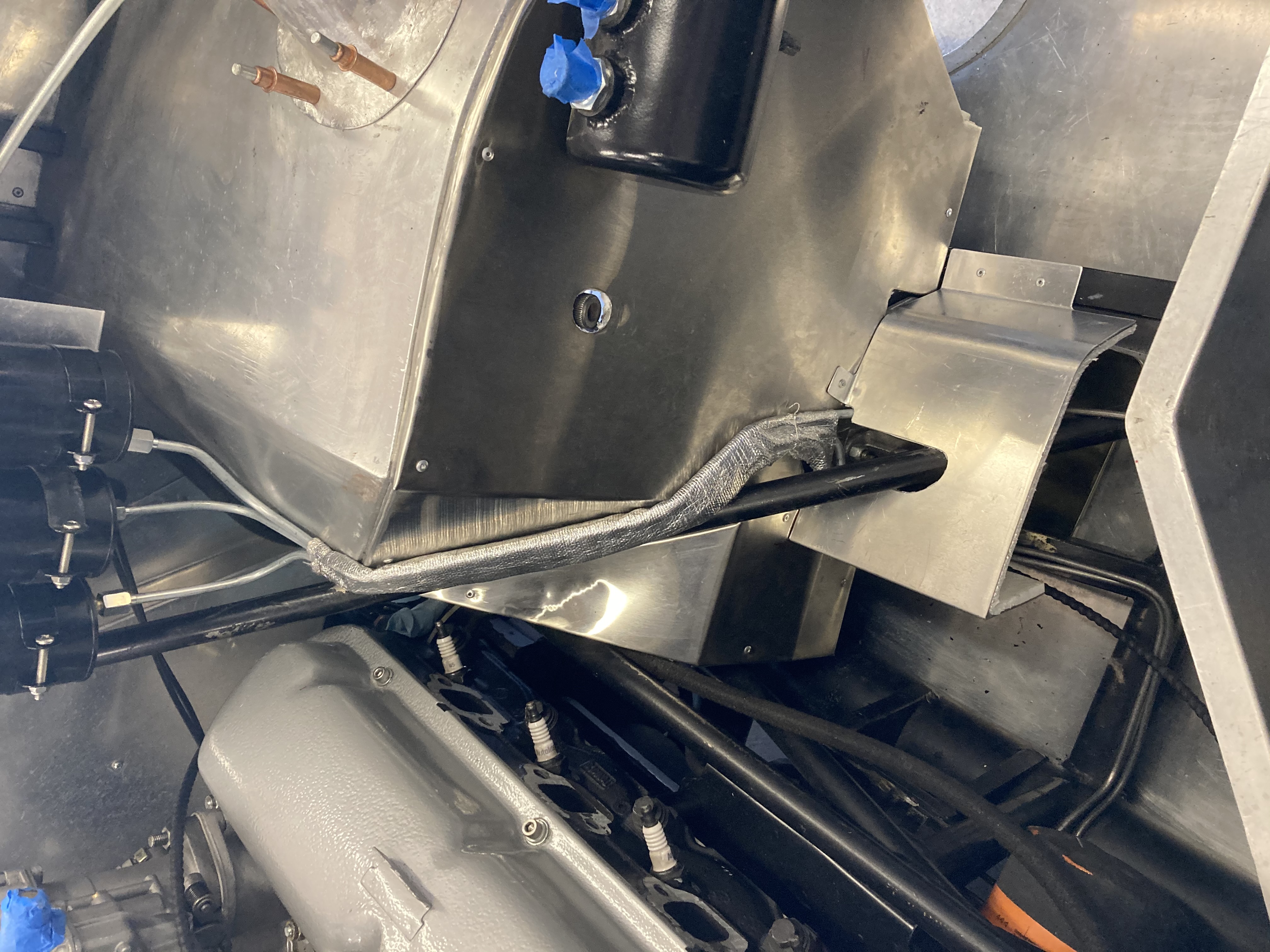
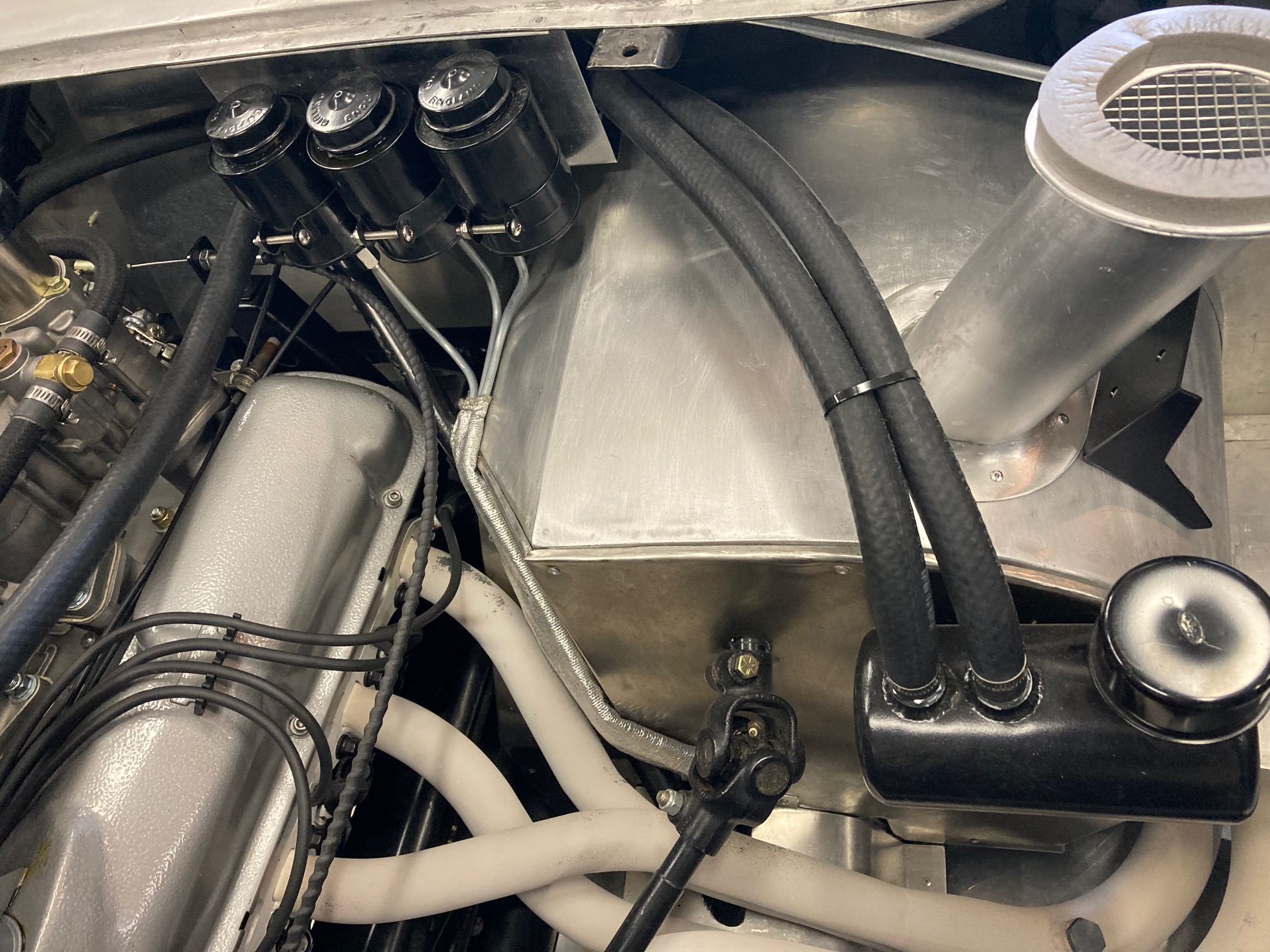
One final aspect of the interconnection tube rerouting was to install heat shielding material around the steel tubes as well as fabrication of a shield over the master cylinders to help them survive the radiant heat from the headers. Heat isulation was also installed on the under side of the master cylinder's shield.
The almost complete insulation is shown in the following two photos.

