Welcome to Our Garage
Daytona Coupe, 289 and 427 Cobras
-37-
Daytona Coupe Cobra -
Transmission Crossmember -
Modifications
As I noted very early in the history of building my Daytona, installation of the complete engine and transmission as a unit was impossible with the original chassis configuration. This was due to a number of factors; the engine and transmission are mounted lower in the chassis, the larger oil pan with minimal clearnace above the 3" diameter chassis cross tube, the triangulation tubing located above the transmsssion and finally a triangulation tube and floor behind the switch panel. All of these contribute to the need to install the engine and transmission as separate components when used in an original Daytona chassis configuration. (If anyone has photos showing installation of the engine and transmission being installed as a unit assembly I would love to see them.)
Before installing the Weber engine in car, I again resorted to a review of photos of the original Daytonas in situations where the chassis details could be be more easily seen. In all of the photos I have seen, the crossmember directly behind the transmission mounting bracket has been modified tomake it slghtly lower. All of the cars varied, but they all had the modification to the crossmember in one form or another. It appears that the top of the crossmember was beaten with a large hammer after being suitably softened by an oxy-acetylene torch. Remember these cars where race cars, so sometimes finess was not in the equation. The apparent goal was to provide more room to for the transmission installation.
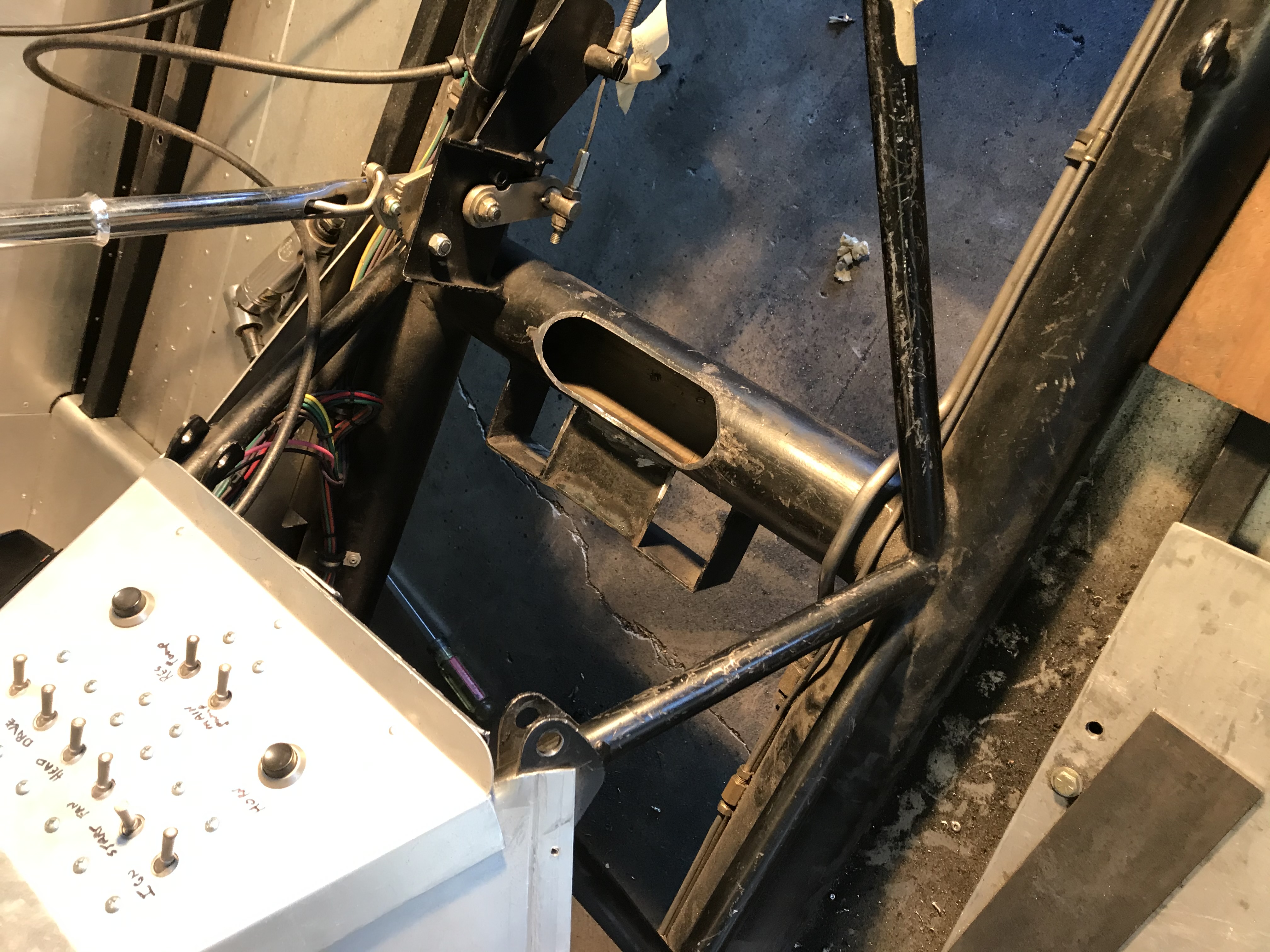
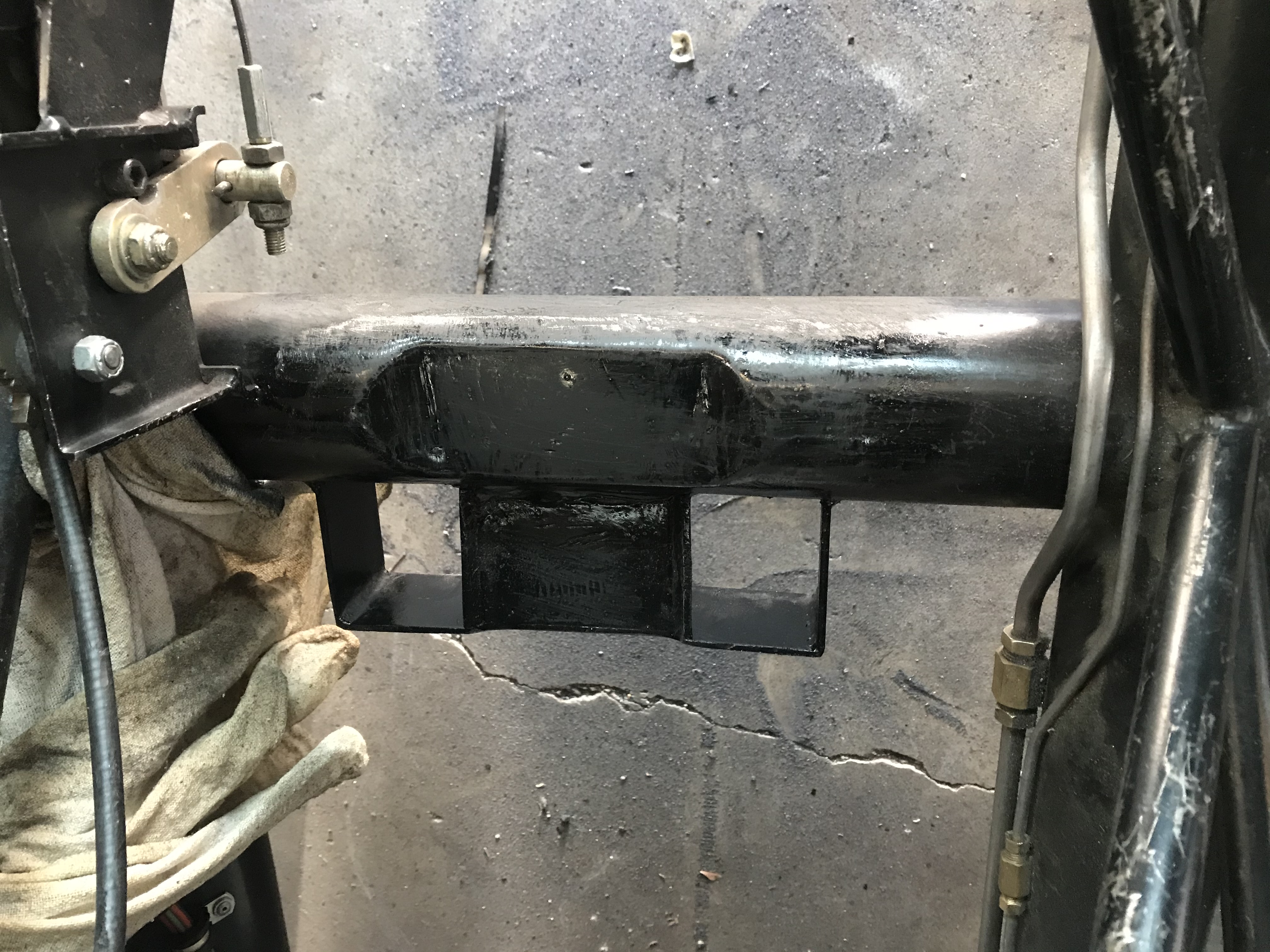
I decided to recreate the original crossmember modification (although I did try to use a slightly more refined method in lowering the center section of the crossmember). I cut a section out of the tube and welded in a new lower filler piece. The first photo shows the cross tube revision in progress and the second shows the tube after the surgery.


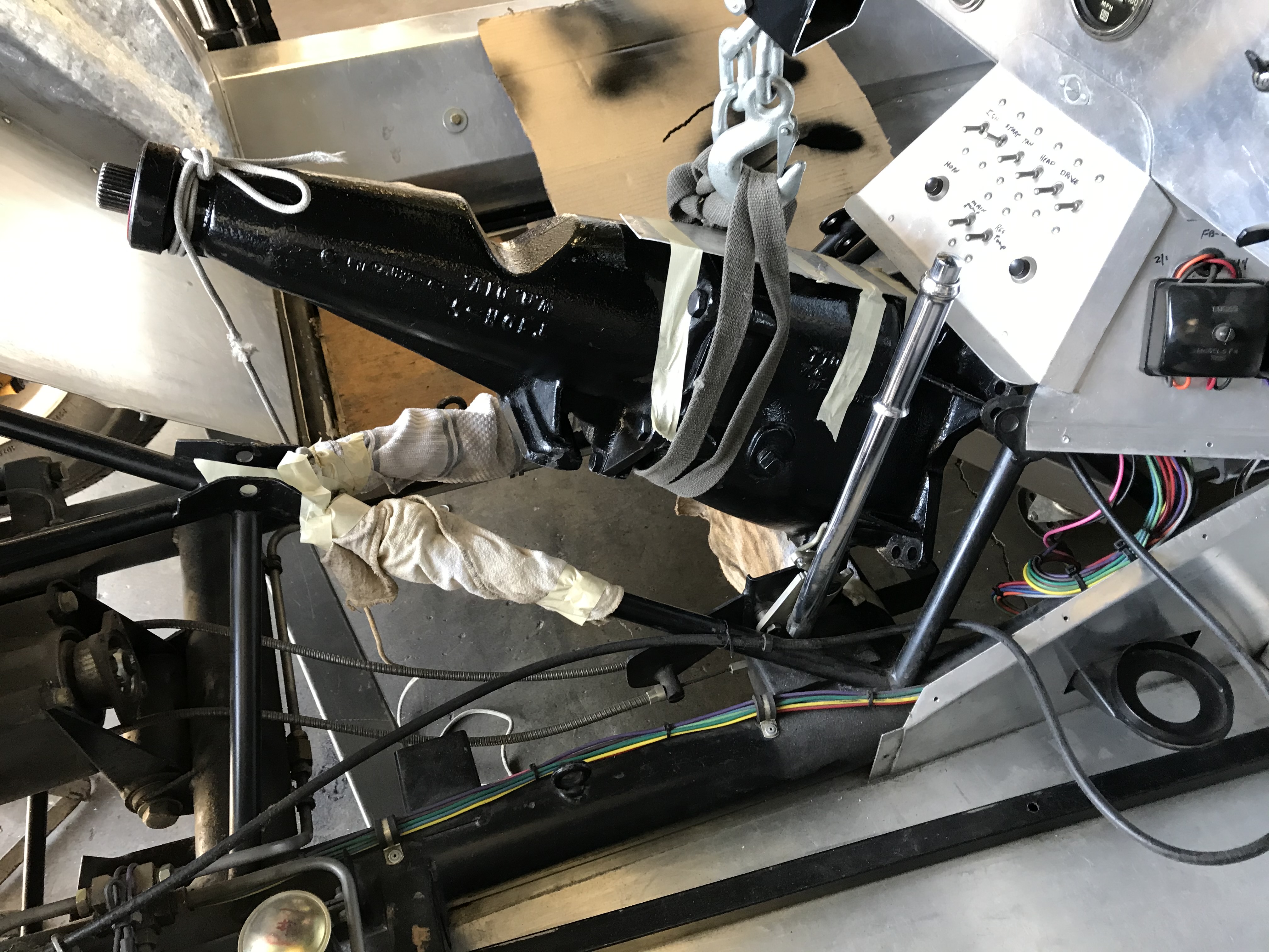
These modifications still require separate installation of the engine and transmission. However, the transmission installation is now a little easier because of the extra "wiggle room" adjustment provided by following the original Daytona chassis design. I'm sure that the Shelby team installation approach (no doubt employing two strong young guys) was diffent than mine. However with appropriate rigging of the engine hoist and some padding to prevent colleratial damage to the interior, I got the transmission installed single handedly and with no mishaps. The following photo shows the transmisison heading into the final stretch.

Footnote about potential solutions
As a footnote to this section, it appears that at least two of the most accurate Daytona recreation manufacturers have incorporated a removable section in the 3" transmission crossmember to minimize the difficultiies of engine and transmission installation and removal.
Several variations are used, but in general, the center portion of the crossmember (which holds the transmisson mounting bracket), is cut away and the remaining 3" crossmember "stubs" are modified by adding a stepped section to the remaining tubes. A new removable section of the 3" crossmember with a matching "step" section is fabricated and attached with bolts to the side tube stubs.
The result is the center portion of the transmission crossmember (including the transmission mounting bracket) may be easily removed. With the transmission crossmember removed, there is adequate room to install the engine and transmission as a unit or to remove / install the transmission (without engine removal) from under the car. This approach appears to be both conceptually simple and effective.
At some point in the future I may adopt this removable crossmember approach on my car. However, for the present I will stick with the original Shelby build team design. After all, how many times do you need to change an engine and transmission on a street car?